Working with the Pumpkin Patch at the church I thought it would be cool to have a punkin' chunker. So one weekend with the kids where here I pulled out some old aluminum beams that
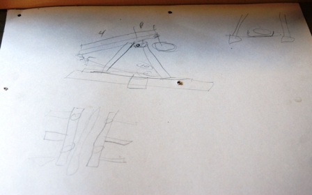
used to hold up the roof on my old sun porch (see Spa Project). I did a little research before hand and determine that the optimum arm configuration was about 2 to 1. The beams were
right at 10 feel long so I figured we could make the fulcrum point at the 8 foot mark. From this I was able calculate the short arm (4') and the hanging weight distance (2') and this
gave us the height requirement for the fulcrum point. First order of business was to pull out the metal components and to explain to the kids how we were going to build it and we
drew up a quick set of plans.
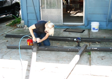
Once we had the metal out of the bushes behind the garage, we laid out the first side section. It is a simple A-Frame construction desing. So we laid out the first lower footing
pieces and then cut the risers to length. Laying the risers on top, we used various angle brackets to secure it in place. To secure the components to gether we used self-taping
sheet metal screws. All the metal was either from the old sun porch roof or an old bed frame I cut up and other various pieces of metal I had laying around.
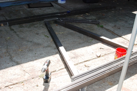
You can see in this photo that we didn't concern ourselves with exact measurements. By using a cross support on the top of each A-Frame, the a frame legs could be off an inch or
two and it wouldn't matter. We simply laid out the pieces and then insured that the top brace was parallel with the ground supports and that sufficed. We made sure that the distance
from the top of the support bracket was at least 7ft from the top of the foot pieces were in order to clear the throwing arm and weight set up.
In order to insure semitry (sp?) between each side, we simple laid out the pieces on top of the existing side. By doing this we were able to lay out the pieces and mark them as
opposed to measuring and trying to keep track of the numbers and or calculations. It was also at this time we began to fully realize the size of the machine we were building and
our excitement about seeing it work was overwhelming!
With each side complete, we then stood up one leg and affixed an 'out-rigger' support to the lower foot component some what close to center of the A-frame. Then we cut a few
pieces of angle iron for the braces. While some one held a level to the A-Frame to keep it as close to vertical as possible, we attached the angle braces to the A-Frame and the
out-rigger. That side then became free standing and we did the other side the same way.
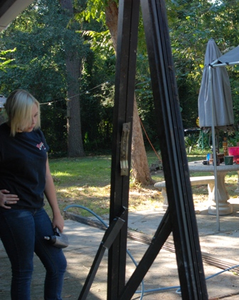
Both sides complete, we found a piece of 3/4 galvanized pipe that we decided would be perfect for our fulcrum swivel. This pipe was then placed on top of the two A-Frames and
they were positioned in such a manner to support the pipe with room on each end. Now was the time to stop and evaluate how everthing was going to fit together. First we measured
the clearance from the ground. Then we discussed and decided upon the distance the two sides should be apart from each other. A lot of discussion was done at this stage to insure
we didnt' build something that was 'almost' right. Besides, I was beginning to run out of material and I really didn't want to have to buy anything!
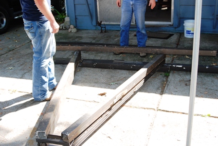
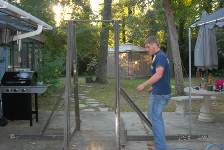
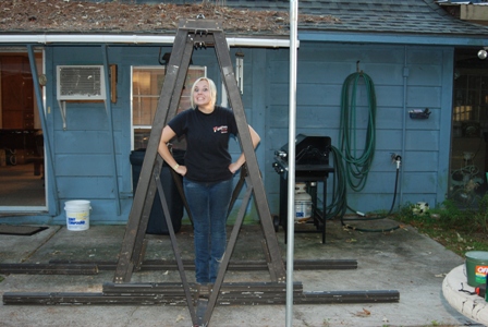
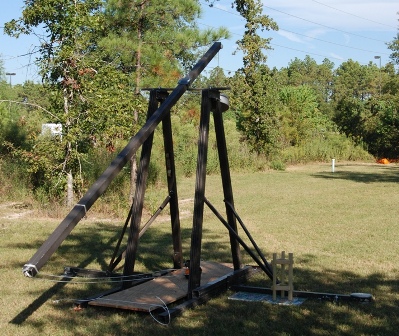
Once all the discussion was completed, we then turned our attention to building the cross pieces that would support the loading bed and the throwing arm itself. In this photo
you can see the size of our machine. Megan is about 5'8 and you can see how she can easily fit under the point where the fulcrum would be located.
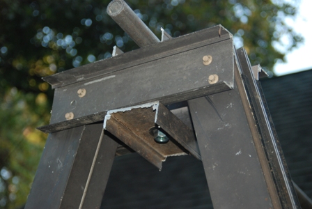
Before we started on the throwing arm, we put in the place the fulcrum supports. We purchased an eye bolt from the local Ace Hardware store that had a shaft long enough to span
between the upper and lower edges of the support bracket and the eye hole large enough to fit the fulcrum pipe.
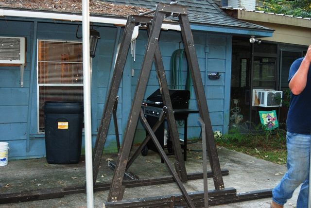
Here is a better view of the upper components and the fulcrum support. As you can see there really isn't a lot of extra bracing or gussetting on this machine, while building it
I was constantly thinking about the stresses that it would have handle. However, I figured even if we got one or shots off and it tore itself apart.. at least it fun building it!
So we forged ahead.
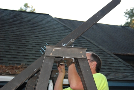
Next order of business was mounting the throwing arm. As determined earlier the fulcrum location was marked on the throwing beam at a distance 8 feet and we simply used two
very strong u-bolts around the fulcrum pipe and through a cross plate on the other side of the beam. This design prevented the need to drill holes in the throwing beam and possibly
weakening the beam. Again, my concern was for the machine last at least a few throws!
With the throwing arm made, we then created the sling attachment and ring release. One end of the sling is tied permenantly around the end of the beam and the other end is tied
to a metal ring. A release pin was the fashioned from an old tent stake and attached to the beam. There should be about a 30 degree angle on the release pin as it is this angle
that determine when the pin slips off and thus releasing the projectile. Too little of an angle and you get a lot of height but no distance. Too much of an angle and you get no
distance at all. This pin should be stiff enough to resist bending but 'weak' enough to all for field adjustments.
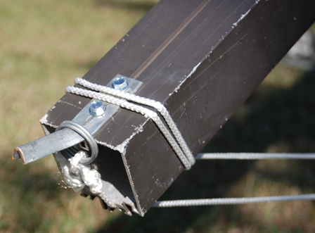
We tried various renditions of the release trigger with sometimes commical results. This photo shows the final working release design. Simple is the key here, there are two
S-hooks that were attached to the throwing beam about 2 foot from the end with the ring release pin. Two holes were drilled into a small angle bracket and through one a long bolt
nut was attached and a pull string tied to the other. Two separate ropes were then tied to the floor bracing on the end of the base foot, one on each side, and two similiar S-hooks
where then tied on them. To set the trigger the throwing arm was lowered into firing position and the two s-hooks from the base were place IN BETWEEN the two S-hooks tied to the
beam. The trigger pin was then insert through all four hooks and the arm slowly release until the pressure of the arm was holding the pin place. Firing was a simply matter of
pulling the trigger pin out.
When we built the machine, we did not have the desired components for the drop weights. THerefore we used what we could find and that consisted of an old wire flower basket
and bricks. The sling was made from an old piece of canvas beach chair. Our first trial shot was exciting and commical. we worked through the bugs and soon had a full throw
completed although the weight was barely suffient to move the arm. But the machine was complete and working!
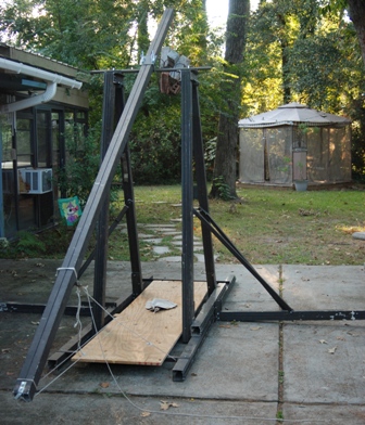
A week past between the completion of the machine and the pumpkin fest where we were set to show off our machine. In this time I refined the drop weight components by using
a length of the cable from an old dog tie out, a section of galvanised 3/4" pipe and some bar-bell weights. This set up allowed me to easily add or remove weights and facilitated
moving the machine. I also refined the sling using a strong piece of canvas. This is a photo of the machine just prior to it's first real pumpkin chunk.
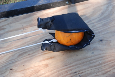
The sling was made by interlacing the rope through the ends in such a manner as to cinch it up much like a purse string. This insured a strong connection but also created a
pouch of sorts to better cradle the projectile. When loading the machine care should be taken to insure that the sling ropes are not tangled and the rope with the slip ring is
on the bottom. Also, safety is a HUGE concern here. You can't really load and place the projectile until the machine is in the firing position which means the weight is now
suspended approximately 7 foot above where the project is to be set. We were using 75 to 85lbs of weight and this process required a constant eye on safety.
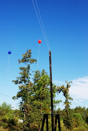
This photo was taken at the top of the firing arch. You can see the outstretched sling ropes. Adding up the lengths, the fulcrum point was 7ft above ground, the long side
of the beam was 8ft and the sling rope was 6ft, this came to a total release height of 21ft. With this set up we were tossing 5 to 6lb pumpkins to a height well over 40ft and
a distance ranging from 50 to 65 yards.
This first video posted on YouTube is the actual building of the trebuchet. There are more photos and more text based information in the video about the building process.
This is a video posted on YouTube that shows the machine in action. The first throw goes as planned and travels about 60 yards. The second throw has the pumpkin leaving
the sling pre-maturely and going backward and ending up in the 'pumpkin patch'. Thus for safety you need to keep the front and rear clear of people and/or objects you don't
want hit by the projectile. Also, a long trigger string is suggested as the machine is carring a lot of force and it can tear itself apart at anytime.