Spectra IV  Repair Page 2

|

|

|

|

|

|

|
|
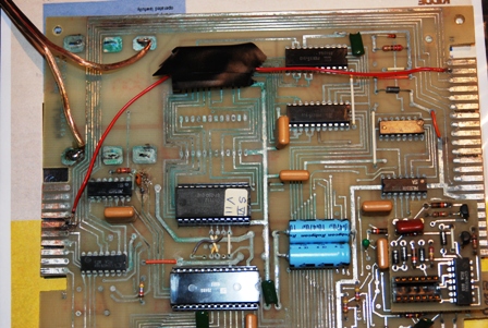
Obvisouly there is something wrong on the CPU circuit board. I decided that I should check continuity on all the printed circuits that were affected by the battery leakage. So I got
out my DMM and started probing. As I was doing so I noticed that one of the edge connectors had a circuit over to the edge connector beside it but no tracing on the top so, so flipped
the board over and sure enough there was a tracing from that point to another chip. So it dawned on me that the circuit designers used the connection points as a way to transistion a
circuit from one side of the board to the other. Eureeka! Maybe that circuit that I was wasn't used was used after all. So I flipped the board back over traced the bad circuit and sure enough, there was a tracing on the other side of board at the 'unused' connection point that led to a pin on a chip! SO, I now realized that I need to repair that circuit. First I tried to soldier a small wire onto the circuit tracing at the point it was bad. Unfortunately this was going to happen for me. So I got a small piece of wire and stripped both ends back. I then soldiered the wire from connection point to connection and test continuity and all was good! |
|
|
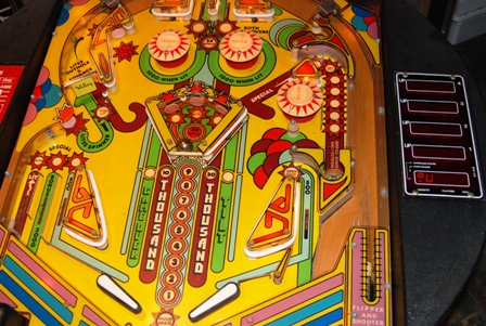
I then repalced the board back into the card cage and connected all the cables and the battery pack. I made sure the Play/Test/Set switch was in the play position and switched on the
machine. And ta-daaaahhhh.... same thing. Just a continous series of tones. However the display board show a '1' in the top most disply group and some other characters in the lower
display group. The photos to the left shows what is on the display while the machine is singing it one long beep'n song. Of course she looks good with all the lights working, plastic cleaned up and the rubbers replaced! |
|
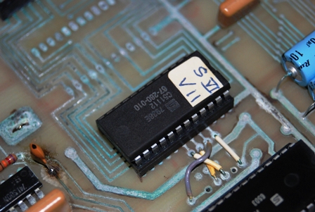
In my quest for answers to my problems I contacted a group that creates Virtual Pinall MAME ( http://www.vpforums.org/ ) replicas to ask them if they knew the start up sequence on one of these machines. The gentleman
who responded was very gracious and was very interested in retreiving the code from the CPU chip in order to replicate the Spectra IV. I decided to assist he for several reasons, first
is my chip could be 'read' we could determine if the CPU bad or good. Secondly, if we did manage to get the code off the chip, that would mean I would have a 'back up' copy of the code
in case during my attempts to fix it I frie the CPU. And last but not least, if we were able to read the code, this could help determine what the machine is trying to tell me with all
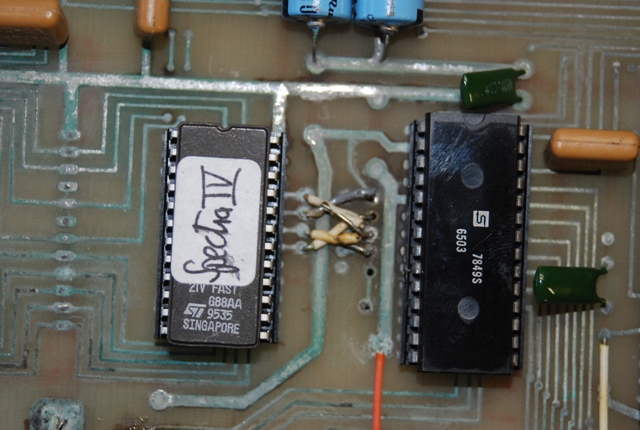
it's beeps.. The photos to the right is the CPU chip showing the brand logo (Sektra) and the chip number. I believe the paper label is the version number of CPU code. |
|
|
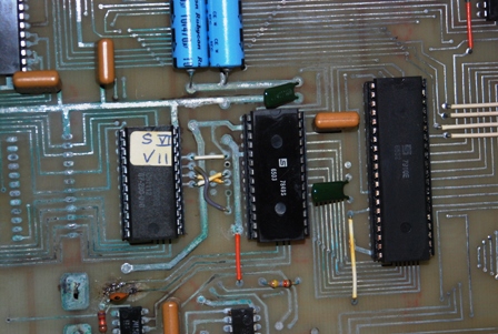
For completeness, this photo on the left is of the full set of CPU, ROM and Timer chip. |
|
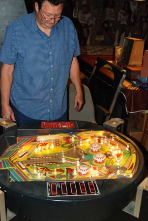
It's been a struggle... today is June 13th and I have had very little if any success with getting my machine to run. In my search for others with a Spectra IV I was surprised to find
someone who has a Spectra IV and about 45 minutes from me. Mr Ferguson is the owner and curator of the Lone Star Pinball Association / Museum and he allowed me to come by one evening to
check out his machine. After fiddling with it for a few minutes, it was displaying the same characteristics as my machine. Dan is shown here looking at his machine as we tried to make
it work. Dan has quite a collection (150+) of pinballs, arcade games and gaming signs. His website is found at: mypeoplepc.com/members/lspa/lonestarpinballassociation/index.html Dan graciously allowed me to abscond with his three program chips to which I sent off to get read. |
|
|
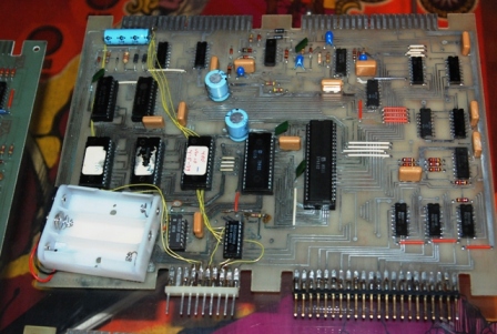
As you can see in this photo, Dan's machine had a much higher level of corrosion damage and the previous owner had done an extensive amount of work on the board. We have not idea if the
machine has ever worked in the condition it was in. Dans chips and my single chip made the trip back out the Visual Pinball guys and through extraordinary efforts of several people they
managed to get a good set of working code. They then attempted to put the code back on my chips but it would not accept the code. The good folks then found a chip that would work and put
the code on it for me and sent the chip to me. Unfortunately, they were unable to program Dan's chips. Receiving the chips, I put them back in my board and attempted to bring up the machine
but alas it was not to be. It is late so I must be off to sleep so I can work tomorrow to pay for this habit! More updates soon.. but you should know that at this point I don't have a working machine. |
| The new chip with the new code didn't seem to work on the machine but it did seem to be a little bit better than it was previously. From there I made a few inquires back to the VP and it was determined that the pin configuration on the new chip was different from the previous chip so it was suggested that I re-arrage the jumpers to correct this problem. The photo on the right is my feeble attempt to do so... nothing smoked and after putting it back in the game it did seem to do more than it had before... but still didn't come up and do what it was supposed to do. |
|
|
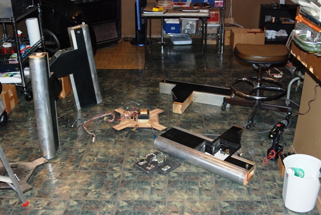
My next thought was that the power being delivered may not have been the correct amount. So, I totally disassembled the table so that I could get to the power supply system. To do this, you first remove the playfield. Then looking down by the rotation connection area you will see a hole just to the outside. Rotate the tub until 1 of the 4 flat head concaved screw heads appears and remove it. Then rotate the tub the next 3 screws removing each in turn. Lift the tub up and disconnect the power supply cables and the tub can be set aside. On each leg there are 2 bolts that pass through the center + portion and screw into the legs. Remove each of these and the associated leg... some help is require or else prop up the center portion as you remove the legs. With the bolts removed the center + portion comes apart into an upper section of just wood and the lower section which has the power supply system connected to it. Using my multi-meter I checked all the voltages and they seem to be with in a resonable level. So.. the power supply isn't the problem.. but it was fun to learn how it fit together! |
| The lower power supply system simply does the power transformation from AC to DC. There is another filtered regulated power supply component that is bolted to the side of the card cage. I tested voltage there and found that my 5v was less than 4.2v and that the capacitors appeared to have issues. So I replaced them and the voltage increased to a steady 5v. I plugged the playfield back in and tried the game again.. still now work but it did appear to 'wake up' a bit more. Each step is bringing me closer! The associated photo is the power transformer that is under the tub. The wiring goes to the on/off switch, 3 fuses and a 'high / low' switch for changing the voltage to solenoids. |
|